top of page


The technical description and drawings:

The double UV light box is made of 12 actinic 8W Philips tubes (16 mm diam, 29 cm length), 6 tubes on both sides.

The box will be made of 10 mm thick ply wood and 5 mm thick MDF.

The front control panel will be made of 2 mm thick aluminum plate.

It will include all the necessary electronics to automatically control the expure time.
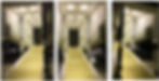
 

The box:

Both the ply wood and the MDF are cut according to the technical drawings.

They are then screwed and glued together to create the two sides of the UV light box.

The inside of the boxe where the 12 actinic 8W tube will be attached is made of 2 mm thick styrene.

The 24 plastic tube holbers will be fixed (not glued) inside the 24 holes in the styrene plate.


The lights:

12 actinic Philips tubes, 24 plastic tube holders and 6 converter (1 for 2 Actinic tubes).

This is how the 6 converters are screwed inside the UV light box.


The electronics:

The front control panel electronics is composed of:

1. AC/DC adapter (transformer): Input: 100-240Vac 50/60Hz, Output: 12Vdc 680mA

2. Main red switch ON/OFF with light

3. Trigger button

4. Plug for power supply

5. Adjustable 12v DC digital timer relay control with display

The front control panel made of 2 mm thick aluminum plate.

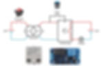
This is the technical drawing for the wiring between the actinic tubes and the converters.


Painting the box:

First layers of white primer.


Stay tuned as there will be MORE TO COME...


Updated: Mar 3, 2020


Ideas and technical drawings:

This part has been largely inspired by the fantastic job that Jason Keith has done on 3D models (Shapeways) and the movie sets.

Image from Jason Keith (Shapeways)

I started with technical drawings that I will use as template for the customization. Templates can be found in the download page.


Preparation of the front wall:

I start with the preparation of the front wall provided by the Deagostini kit:

  1. Drawing the location of the new holes according to the template;

  2. Creating the holes.


Scratch build of the extension for large pipe:

I start building the front wall extension to fit the main pipe (22 mm diameter).

I started drawing and cutting the 5 frame members in styrene plate (1.5 mm) according to template.

I then scratch build of the details along the different frame members on both side (at least for 3 of them) with rod of different diameters, guitar/bass strings and any styrene I could find. The edges of the frames were done with U shaped piece of styrene.

Scratch build of the shelf details above the big pipe with styrene.


Stay tuned as there will be MORE TO COME...


Updated: Mar 2, 2020


Ideas and technical drawings:

Technical drawing and picture showing how much space there is between the moving ramp driver (green) and the fixed ramp ceiling (red). Amongst the 4 rows of lights, only 3 do not have much space: the one before the ramp driver axis has plenty of space. However, the 3 other rows of lights have between 3.6 mm and 5.6 mm of space when the ramp is down. The estimation of the available space is important for the lights and wires between the moving ramp driver and the fixed ramp ceiling.

In addition to light the ramp ceiling, I am planning to light two extra spots along the ramp wall.


Preparation of ramp ceiling:

The brass pieces, which created an effect that I liked, have been removed as they take too much place above the ramp ceiling for the lights.

They will be replaced by Ø 4 mm styrene tube to gain space above the ceiling to accommodate Chris Holland lighting.

Here are the small pieces of styrene tubes, which finally create an effect that is not too bad.


Sliding cover for the ceiling lights:

As I want to have a maximum of things removable for repair or replacement (i.e. lights), I had to find a solution for the 8 ramp ceiling lights with the constraint that the minimum space I have between the moving ramp driver and the fixed ramp ceiling is 3 mm (see technical drawing above).

I therefore decided to create a sliding cover that will hold the eight lights and wires. The lights must be glued on the sliding cover and fall exactly where the 8 ramp lighting holes are located.


The Chris Holland's lights:

The customized lights that Chris Holland created for this project are very tinny SMD leds (less than 1 mm wide). 8 leds are for the ramp ceiling and 2 are for the ramp walls.

Leds are then glued with CA on the sliding cover. The wires have been temporally Scotch taped, they might be glued at a later stage after all tests are done. It was a real pain to glue the leds without damaging them, they are so tinny. Thanks Chris Holland, it must have been a real burden to solder them.

Here is the sliding cover with the leds and its ramp ceiling back side counter part. Light is OFF on the top picture and ON on the bottom picture.

View from the ramp ceiling side with light holes. Light is OFF on the top picture and ON on the bottom picture.

Below is a short video showing the lights in action...

Maximum protection for the tinny leds and wires using 0.5 mm styrene sheet.

Lights in place inside the falcon ramp (quick check).

... with the hydraulic lifters.

Photo montage to compare the modified ramp with the movie set ramp. Note that the movie set ramp is larger than the Deagostini ramp.


Stay tuned as there will be MORE TO COME...


bottom of page