top of page

Updated: Mar 2, 2020


Goal of this customization:

The goal is to reproduce the ramp access to the corridor as well as the walls shape and details as close as possible to how it was used in the movie sets and drawn on blueprints, considering the space and geometry constraints given by the Deagostini model.


Cutting the frame:

The frame of the ramp area was removed using a Bremel like tool with a thin cutting disk. The red areas and circles show where the frame has been cut.

Vertical parts of the frame were cut at the mid height as I want to keep them for both fixing and strengthening the modified ramp walls. The frame that was removed is kept for fixing the translated ramp motor to the added ramp walls later.

I added 5 extra 2-hole connectors (yellow) to consolidate the frame around the ramp access area. A Ø1.8 mm drill bit was used to fixe the extra 2-hole connectors to the frame. This is enough for screwing the Ø2 mm black Phillips button head screws without any threading.


New wall structural elements:

Below is a technical sketch of the customization before playing with styrene and scratch build the ramp walls. Templates can be found in the download page.

The templates are then used to draw the wall main structure on styrene sheets.

The styrene sheets are then cut and the parts glued to create the main walls in which details will be added later.

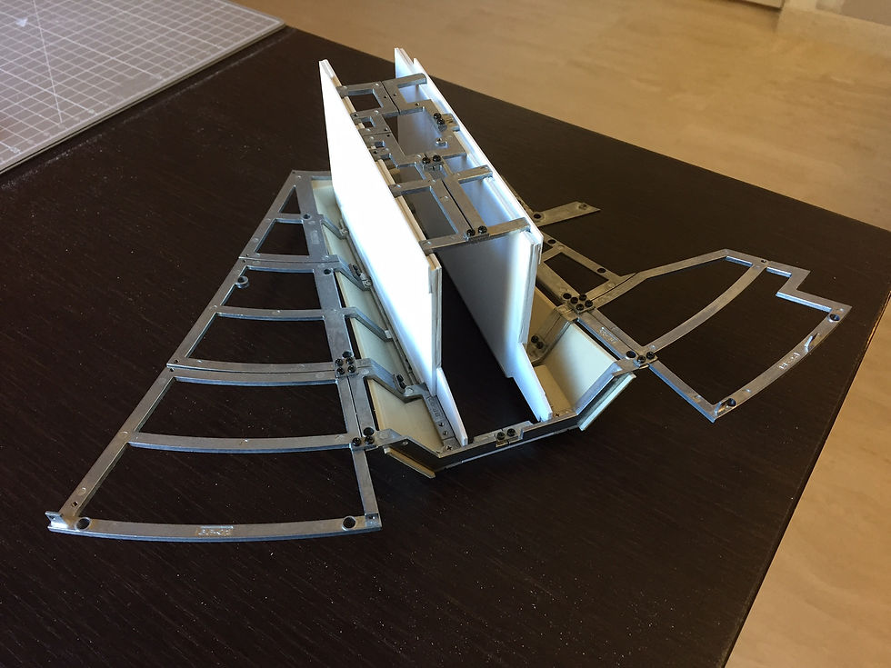
First verification of the main access ramp modification and adjusting the different parts to produce the best fit.


Ramp walls customization:

I am filling the gaps with styrene (in yellow) to improve local imperfection in the customization.

Here are the two ramp wall almost done with 100% styrene. For the details, I used a symmetric pattern based on available blue prints, except for the greebles. The circular cuts are for the extra corridor part that we should see when the ramp is down.

The customized wall in place within the ramp area.

I then added some holes for potential lighting and two holes on each wall for the axis (hinge) of the new ramp mechanism.


Ramp ceiling:

The ramp ceiling has been built with 2 mm thick styrene sheet, rods (1/4 circular section) and small rivets for the lights. Here is where I found the small rivets: AliExpress.

Here is the ceiling in place with the walls.


Ramp corridor access:

I started with a plan as I needed to solve space problem with the addition of the new ramp and associated corridor part.

I then used of a spare corridor from the port wall and cut it to fit the modified ramp.

I glued the upper and lower modified corridor parts and add a styrene floor. I cut the base of the corridor to fit the lower turret ring frame (another space problem to solve!) and open a big hole for the ramp access.

I then added customized cushion pads inside the corridor. The cross on the back central cushion pad is the location of one light.

The ring pads have been filed sharp on the outside to (1) reduce their size as they will be doubled with the mirror and (2), attenuate the gap between the pads and their reflection and give the effect of single pads. Also from the movie set, it seems that the pads are more rectangular than square.

I decided to add two circular mirrors (Ø 50 mm) on both ends of the extra corridor part.

Below is the extra corridor part in place to check the fit and rendering.

Just for the fun...

As I was not really satisfied with the circular mirrors that I placed on both sides of the corridor up the Falcon ramp, I decided to test mirror sheet. Comparison between the classic glass mirror (right) and the mirror sheet (left). The mirror sheet has a much thinner transparent plastic cover than the classic mirror, which has a thick glass cover.

The advantages of the mirror sheet is that it reduces the gap caused by the mirror thickness, it is easier to cut the shape we want, it is as sharp as the classic mirror, diffraction is reduced, it is lighter. The drawbacks are that the plastic cover can be scratched more easily than the glass cover and that it has to be glued to a flat hard surface to avoid any distortion (here I am using 1 mm styrene sheet).

With the two mirrors...

Stay tuned as there will be MORE TO COME...


Updated: Mar 2, 2020


Ideas and sketches:

The ramp modification started with few sketches and drawings on paper as well as with the analysis of Forums and Blogs from hobbyists who have been working on the Falcon ramp customization.

Then, few technical drawings on computer to finalize the ideas, check the feasibility and find the correct materials for the customization. Templates can be found in the download page.

Below is a short video showing the 3D animated ramp mechanism proof of concept. This is an animation, done in Fusion 360, to test the modified ramp mechanism with the motor translated upwards. The motor should move the red part which should in turns drive the green ramp up and down.

To start the ramp customization I built the entire frame of the Falcon to have a clear estimation of the available space inside the ship for the ramp customization.

As I am planing to displace upwards the motor that opens and closes the ramp, I needed to know how far I could go.


The ramp customization:

The Deagostini original ramp hinge will be replaced by a new one.

The new hinge is from the RC world. Its size is 20 mm x 37 mm.

Then I modified the ramp itself. The hydraulic actuators spots on the ramp were removed (red), displaced or added (yellow), or simply kept (green). Space was made for the location of the new hinge (yellow).

Below is the modified ramp with new hinge. New hydraulic actuator locations are based on Star Wars blue prints and few snap shots from the movies.

The next idea is to remove the upper U or T shape observed on the Deagostini model when entering the access ramp (the picture on the right is from the Deagostini model from Chris Olson). The foot of the ramp that flips down has therefore to be modified.

I decided to shift the rotating ramp foot axis (yellow) upwards. To facilitate the build of the new axis, the blue parts of the ramp have been removed, drilled, new axes installed and glued back to the ramp.

I then added 2 mm thick styrene sheet (yellow) has been glued to the ramp floor.

The ramp foot (in yellow) has then been placed on the new axis. This modification was previously modeled with Fusion360 (upper figures) to verify its feasibility. The only feature that I could not get rid of at that scale is the small relief produced by the foot hinge.

Below is a short video showing the animated ramp foot that flips up and down. This is an animation, done in Fusion 360, to test the foot of the ramp, which flips down and up when the ramp opens and closes respectively. This could be a version that works but difficult to motorize at the scale of the Deagostini model. I am not even sure it was motorized in the movie sets.

I then glued the new hinge, added the floor of the ramp (ABER, engrave plate, PP17) and stair step on the sides using styrene, as seen on the movie sets.

Finally, I scratch built the extra ramp part that will be placed at the entrance of the corridor door and which extend the ramp floor inside the ship.


The ramp hydraulic actuators:

As I was not satisfy the the hydraulic actuators provided by Deagostini, I decided to customized my own lifters. This happened to be really challenging. I first started with technical drawings and the list of materials I am planning to use to scratch build the ramp hydraulic actuators.

The ramp hydraulic actuators have been scratch build and assembled. Below is a new hydraulic actuator compared to Deagostini actuator. The extremity of the Deagostini actuator, which is attached to the ram pivot, is cut and used for the new actuators.

Here is the result one final actuator compared to the technical drawing. It is not perfect but considering the size of it, I am happy with the result.

Finally after several hours of work the 6 hydraulic actuators are done!


Ramp driver:

Technical drawings to design the mechanism that will drive the ramp. I wanted to have a system that lets you adjust the height of the driving front hydraulic actuators. A short video showing the 3D animated ramp mechanism proof of concept can be seen here.

I started the scratch building of the plate that will be linked to the motor to drive the ramp.

I used a spare ramp from the kit reinforced by a 1.5 mm thick styrene sheet. For the axis I used a hinge from the RC world.

I then drilled holes that will be used to place the hydraulic lifter rods. This will help actuators to stay in a correct position during motion of the ramp.

Here is a rear view that shows how this moving plate, which is drived by the motor, is attached to both ramp walls through an axis.

The small piece attached to the ramp driver and that will be connected to the front actuators is so far the only piece that has been 3D printed as a test with an Ultimaker 1. It is glued to the plate that will be linked to the motor to drive the ramp.

The moving part attached to that small 3D printed piece was scratch built with styrene. This part has claws and bolts to hold and fine tune the front ramp actuators during opening and closing of the ramp.

Here is the mechanism in place with driving front actuators only. This is a test to check if everything is well placed and fit properly.

Video of the ramp with the 6 actuators and ramp mechanism.

Ramp (all actuators in place but not glued yet) photos with two different camera focus.

Stay tuned as there will be MORE TO COME...


bottom of page